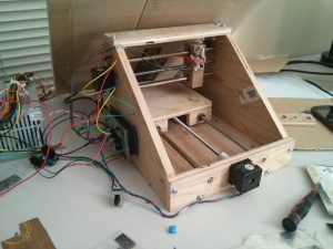
DIY Laser Cutter for PCB Stencils
Friday, 29 March, 2013 18:27 Last Updated on Friday, 29 March, 2013 23:14
20 Comments
Introduction
Are you sick and tired of using a tooth pick to apply solder paste? Are you still using through hole components because you don’t want to deal with soldering surface mount devices (SMD)? If so, this post provides you with guidelines for building your very own laser cutter for cutting PCB stencils. With a total cost of approximately $200 (it can be significantly less if you already have parts laying around), this project can pay for itself very quickly. While you can get “low cost” stencils for your PCBs, they still can be quite expensive if you are only creating one or two boards.The laser cutter can cut very accurate stencils from adhesive backed black vinyl sheets (on Amazon) for ICs with a pitch of 0.5mm (SON-10) and 0402 resistors (and possibly even smaller parts). These stencils are disposable and so cheap that you do not have to worry about using your stencils on one or two PCBs.

It gets better. You can use your RepRap as a laser cutter. All you need is a laser, a laser driver circuit board, and updated firmware (see below). While I built my laser cutter to be a laser cutter and not a 3D printer, I still used the RAMPS for the electronics even though it was built for the RepRap.
Before going onto how I built the laser cutter, I want to give you a quick overview of the design flow once everything is up and running:
- First, I create a circuit board and order it from either Seeedstudio or OSHPark. Eventually, I will be using HackEDA for my schematic designs (go check them out!).
- Next I make sure I have all the components I need.
- Once the boards arrive, I export the gerber files for the stencils from Eagle CAD using a simple CAM processor.
- I then run a custom Python script which reads a gerber file and outputs a G-code file that the RAMPS electronics can understand.
- Using pronterface (a RepRap interface software), I control the laser via G-code creating the stencil
- A few minutes later, a perfect stencil has been created!
- Using a credit card or razor blade I apply solder paste to the board.
- I then manually place the parts using tweezers (sadly I do not have a pick and place machine…. yet).
- Finally, I carefully place the populated board in my toaster oven reflow oven.
- Approximately 5 minutes later, a perfectly soldered surface mount PCB is ready to be tested!

ReplyDeleteVery useful article written, interesting and valuable .Always expecting such a informative blog from you.